Introduction:
A switching charger is smaller and lighter alternative to conventional transformer chargers.
It also allows precise adjustment of the target charging voltage. According to its setting, it can charge batteries of different types and in various modes.
I describe a charger for a battery with 12V rated voltage, but it can be modified to for example 6V or 24V.
Circuit description:
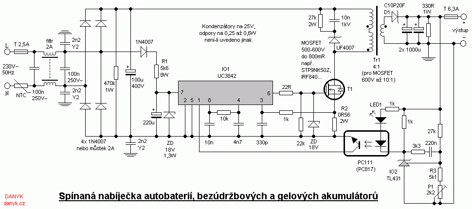
This charger works on the principle of switching power supply. It's built in a similar way as ordinary flyback switching power supply with integrated
circuit UC3842 and TL431. The only difference is that the auxiliary power for IO1 is not obtained from the auxiliary winding, but dropped
from the mains using power resistor R1.
The advantage of such method is that the power supply is reliable in the current mode (does not cycle) and there's no need to use an auxiliary winding.
The voltage is stabilized by circuit IO2. Feedback is introduced via an optocoupler. The target voltage can be adjusted by trimmer or pot P1 (can be set in the range of
about 12 - 16V). Adjust with the voltmeter connected to the output without battery connected. A voltmeter can also be built into the charger.
The current is regulated indirectly by the current sensing resistor R2 on the primary side. This simpler version is sufficient, because the current setting is not as critical as
the voltage setting.
With values in the diagram, the charging current is of about 3.5 A. The charging current can be changed by changing R2 (lower resistance - higher current and vice versa).
Beware of stupid current increasing - the whole circuit must be rated to the desired current.
The charger on the schematic below is designed for batteries with a rated voltage of 12V. You may modify it to 6V or 24V by changing the transformer winding ratio (the numner
of secondary turns)
and some components on the secondary side including the voltage divider.
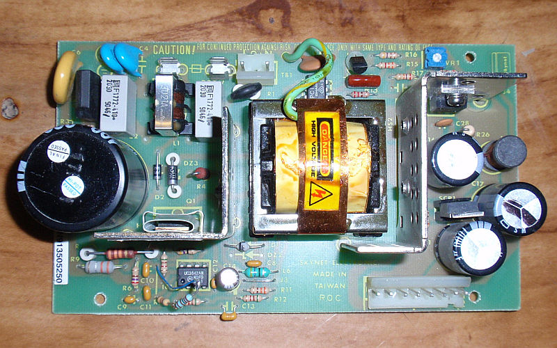
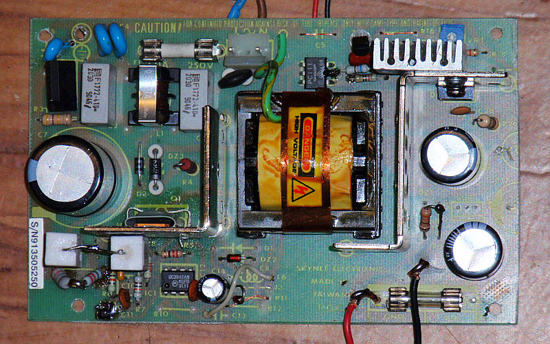
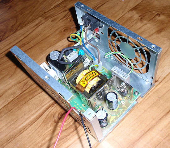
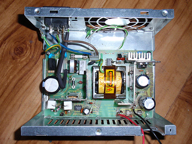
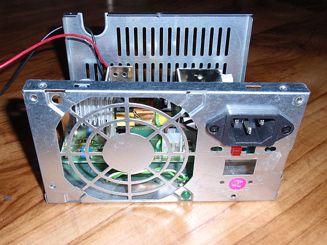
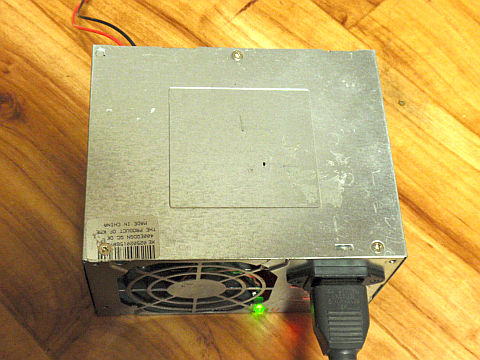
For the construction of the charger, I used a wreck of an old switched power supply 15V / 4.5 A. You can of course build on your own PCB.
I used the original transformer. The transformation ratio is about 4:1 (for a 500V MOSFET). The charger can use any flyback transformer from SMPS of about 12 - 20V
rated for enough current. A 600V rated MOSFET allows to use the trasformer primary:secondary ratio up to 10:1.
Care should be taken that the voltage across the T1 transistor does not exceed its rating (it's recommended not to exceed 80% of allowed absolute maximum value).
Voltage on Tr1 primary (ratio x output voltage) is added to the input voltage (about 325V, that's the rectified 230Vac).
Example: With the transformation ratio 4:1 and 16V output voltage, the T1 sees approx 4 x 16V + 325V = 389V.
The transformer Tr1 must have proper winding orientation, denoted by dots (failing to do so would be destructive).
The working frequency is about 40kHz. LED1 indicates a transition to the voltage source mode.
Transistor T1 is any fast MOSFET with UDS 500-600V and on state resistance RDSon no more than about 800mR, eg IRF840 or STP9NK50Z.
The diode D1 is any ultrafast diode with reverse voltage at least 200V, current 10A and reverse recovery time better under 50ns, eg C10P20F (200V, 10A, 35ns).
T1 and D1 must be placed on the heatsink. Maximum power input of this charger is 65W.
The charging time depends on battery capacity, efficiency of charging process and the initial state of charge.
Example: empty battery with 35Ah capacity would theoretically charge 35Ah : 3.5 A = 10h. In practice it may be 15h, because the charging process does not have a 100% efficiency,
but approximately 2/3, and therefore the time is multiplied by about 1.5 times. The charger can be used for batteries with capacity of about 7 to 120Ah.
Connect the charger to the battery first and then to the mains. Disconnected from the mains first, then from the battery.
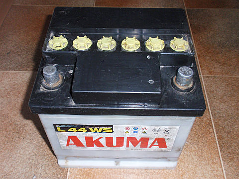
Charging conventional (car) batteries:
When charging conventional (automotive) flooded lead-acid batteries using relatively small currents compared to its capacity, we do not have to worry about overcharging.
If you will be charging up to the gassing phase ("bubbling"), the loss of distilled water is not destructive, because you can refill the water into this
type of battery. If we want to charge with no significant gassing and water loss, set the voltage approx 14.4 V.
The charger can be set to a lower voltage (about 13.6 V) and used to preserve battery (maintenance mode).
Deeply discharged battery can be resurrected by appliying increased voltage of 16V
(disconnect the battery from the vehicle in this mode!). During normal charging is not necessary in most cases to disconnect the battery.
Some vehicles may not like the battery being disconnected.
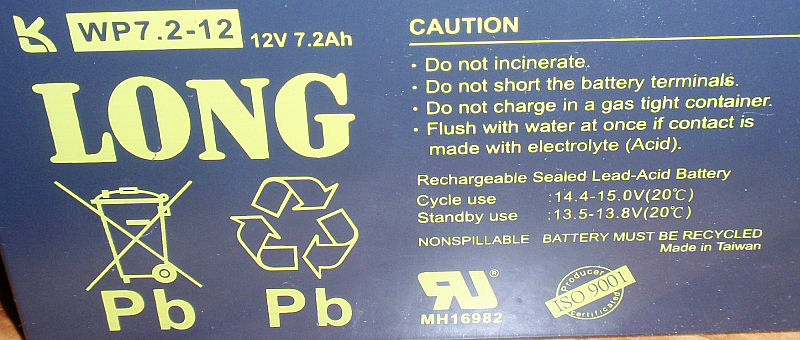
Charging VRLA batteries and gel batteries:
If you charge VRLA batteries (valve-regulated lead-acid) Pb batteries, similar gel batteries (cells) or AGM (Absorbed glass mat) batteries,
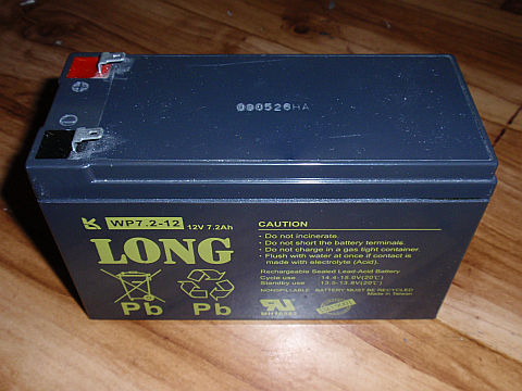
pay more attention to the charging voltage. In these types of batteries, two charging voltages are usually given: 1) Standby use voltage,
which is lower. This is the charging level, for example in an UPS. This voltage can be connected permanently. This keeps battery always charged.
This voltage is in the range of 13.5 to 13.8V for the example battery below.
2) For cycle use, which is higher. The battery is being charged to this voltage when it is used cyclically (charge-discharge).
The battery should not be permanently connected to the charger set to this voltage. For the battery of our the example, this voltage
is 14.4 - 15V. Is it necessary to disconnect the battery after charging in this mode. It is also necessary to take care not to
exceeded the maximum current. Those values are usually written on the battery or in its documentation. These batteries should not be overcharged.