Electronic Halogen Transformer is a substitute for traditional line transformer for halogen bulbs.
(It can of course be used also for non-halogen bulbs and other types of resistive loads who do not mind RF current.)
It works on the principle of switching power supply.
Unlike conventional switching power supply, it does not have secondary rectifier,
because the bulb does not need necessarily the DC voltage. It also has no smoothing electrolyte after network bridge.
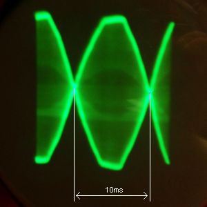
100Hz ripple because the bulb does not matter. Just by reducing ef. voltage by about 30%.
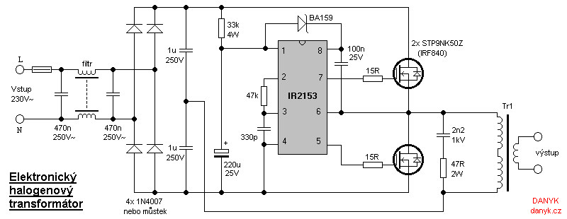
Due to the absence of electrolyte the thermistor is not necessary and it also solves problems with power factor (which is nearly 1). Circuit is designed as
a halfbridge with MOSFETs and driving circuit IR2153, which is equipped with a floating upper MOSFET driver and
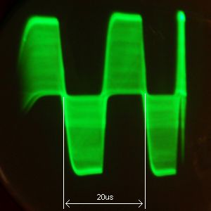
own RC oscillator. Circuit operates at a frequency of about 50kHz. At the primary of the pulse transformer, the effective voltage
is approximately 107V, according to the calculation:
Uef = (Uvst-2) . 0,5 . √(t-2.deadtime)/t
Where Uvst is input line voltage, deadtime in IR2153 is always 1,2us and t is a period, in case of 50kHz it is 20us. After substituting:
U = (230-2) . 0,5 . √(20-2.1,2)/20 = 106,9V.
The voltage reduces by 2V at diode bridge, divides by 2 at the capacitive divider made of capacitors 1u/250V
and finally the effective value is reduced due to deadtime.
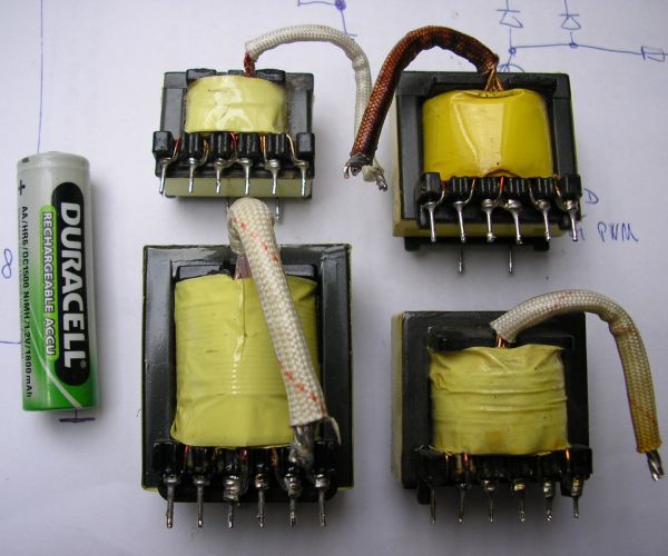
Transformer Tr1 is a pulse transformer ona a ferrite core (EE or EI) and can be obtained from computer switchnig power supplies such as AT or ATX.
The core should have a cross section of about 90 - 140mm2. Number of turns will probably need to be adjusted
depending on the bulb. When calculating the transformation rate, we assume that at the primary is the
effective Voltage 107V (in case of 230V line input). Transformer from AT or ATX usually has 40 turns on primary. Primary is divided into 2 parts, 20 turns each,
one is under the secondary and one above it. This method of winding is used to reduce magnetic leakage.
When adjusting the transformer you will need to unwind the upper half of the original primary and whole secondary. Then replace the
secondary, which will have approximately 2.4 to 3V per turn. For 12V bulb i recommend 4 turns (can be about 4-5). Required voltage
we choose 11,5 V (for halogen bulbs the voltage is usualy selected with reserve).
Transformation ratio is calculated: 107V / 11.5 V = 9.304 .
At the secondary we have 4t, so primary must have 9.304 . 4t = 37t . Because in the bottom half of the remaining primary
remains original 20z, we wind top layer 37t - 20t = 17t . If you can find out what the original number of turns was on the secondary, it will be much easier.
If you find that some of the secondaries has 4 turns, then just simply unwind 3 turns from the top of the primary and you're done :).
A similar procedure would be even 24V bulb, except that the secondary we chose 8-10 turns.
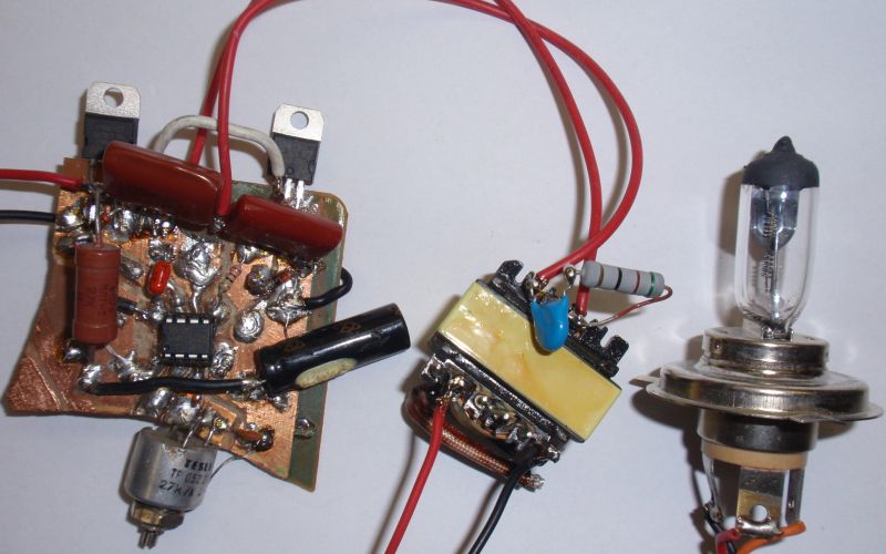
With MOSFETs STP9NK50Z or IRF840 without heatsink this
electronic transformer can be used for output to about 80-100W.
Similarly, it would be with STP10NK60Z, STP11NK50Z or STP9NC60FP.
For more power, use the heatsink and / or more powerful MOSFETs, such as
IRFP460, IRFP460LC, STP15NK50ZFP, STW20NK50Z, STP25NM50N, STB25NM50N-1 or 2SK2837. They should have a voltage Uds 500-650V.
Leads to the bulb should not be
too long, because there is RF voltage and it could cause interference and voltage drop due to their inductance.
Output voltage can't be measured using multimeter.